
This series refer to an older version of LWJGL 3. The updates are in progress.
Contents
Hello and welcome back to the LWJGL Tutorial series. Last time we learnt how to color a triangle using VBOs, we learnt how to pass the color value to the fragment shader. Now this time, we are going to learn about Element Buffer Objects. This kind of rendering is called as Indexed Rendering.
Talking about indexed rendering, we need to understand what are vertices, what are indices, and what is the relation between them, vertices and indices. If you remember the previous tutorials, we defined a triangle using three vertices. Now we are going to draw a rectangle using four vertices. You see nothing special in the last statement? Well there is one thing. In OpenGL, you CANNOT render a rectangle directly, the GL_QUADS primitive is now deprecated.
What we do instead, is we split the rectangle into two triangles and render using GL_TRIANGLES primitive. That means that we need to define \(6\) vertices where you really need only \(4\) vertices. It may seem that two more vertices is not going to effect the performance, but it actually does in a real world complex scene, where there are many instances of models consisting of thousands of triangles. Indexed Rendering is a solution to this problem, where we can reuse the vertices.
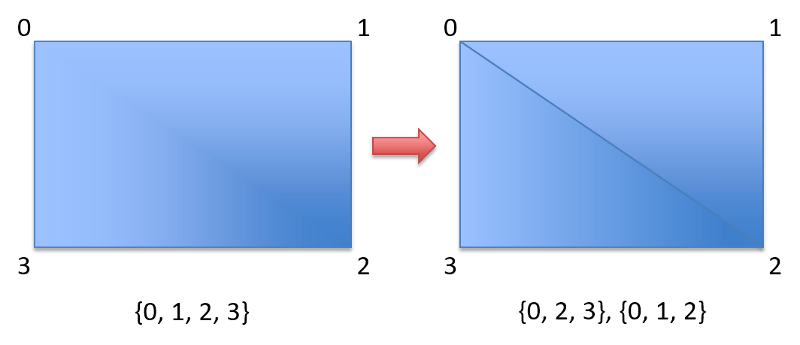
If you see the image above, you will recognise that the second rectangle is a combination of two triangles. It also shares two vertices along the diagonal. What you see in the braces is the set of indices that make up the triangle, and two sets of triangle indices make up the rectangle. If we are NOT using indices, this is how we have to declare the vertices.
float[] vertices = new float[]
{
    // Vertices for the left triangle
    -0.8f, +0.8f,  // Repeated Vertex
    +0.8f, -0.8f,  // Repeated Vertex
    -0.8f, -0.8f,

    // Vertices for the right triangle
    -0.8f, +0.8f,  // Repeated Vertex
    +0.8f, +0.8f,
    +0.8f, -0.8f   // Repeated Vertex
};
You can see that two vertices are shared by the two triangles. If the vertices are specified in this way, the indices will be \(0…5\) for rendering a rectangle using two triangles. Instead, we can reduce the vertices, and specify our own indices making \(4\) vertices and \(6\) indices. This is better than \(6\) vertices and \(6\) indices. Let’s now see the reduced vertices.
// The vertices of our Rectangle
float[] vertices = new float[]
{
    -0.8f, +0.8f,  // ID 0: Top left vertex
    +0.8f, +0.8f,  // ID 1: Top right vertex
    -0.8f, -0.8f,  // ID 2: Bottom left vertex
    +0.8f, -0.8f   // ID 3: Bottom right vertex
};
Now that we have a custom indices, we have to specify the indices ourselves because if we didn’t, OpenGL only draws the first triangle and ignores the fourth vertex. We now create the indices in a short array, shown in the following code. We define six indices, three for each triangle.
// The indices that form the rectangle
short[] indices = new short[]
{
    0, 1, 2,  // The indices for the left triangle
    1, 2, 3   // The indices for the right triangle
};
Now that you understand what indices are, it is now time to tell the GPU that you want to use your own indices, and let it know what are the indices. This is done by using an Element Buffer Object, which is just another buffer object that is bound to GL_ELEMENT_ARRAY_BUFFER instead of GL_ARRAY_BUFFER as it’s target.
eboID = glGenBuffers();
glBindBuffer(GL_ELEMENT_ARRAY_BUFFER, eboID);
glBufferData(GL_ELEMENT_ARRAY_BUFFER, indicesBuffer, GL_STATIC_DRAW);
Unlike the Vertex Buffer Objects, here we don’t see a call to any pointer functions, as we don’t access the indices from the shaders. OpenGL can automatically select the vertices from the VBO based on the indices we specify in the element buffer object. However, we have use a special function call called as glDrawElements instead of the glDrawArrays which we have been using since before. Let me explain it’s syntax first.
void glDrawElements(int mode, int count, int type, long offset);
That is the signature of the function in Java, as supplied by LWJGL. The C declaration is a bit different, except the only changes are using GLenum GLsizei and GLvoid* instead of int and long to support platform independence. This is how it looks.
void glDrawElements(GLenum mode, GLsizei count, GLenum type, const GLvoid * indices);
In my opinion, you can understand the first three parameters as they are similar to the ones in the C version, but you will confuse on the last parameter, as they differ in both the name, and the type. There is actually no difference between them, it is because Java does not support pointers. LWJGL converts it automatically in the JNI. Now coming to the meaning of offset, it is the byte offset between the vertex tuples, which I will explain in the later tutorial. Since now we are not interleaving the buffers, you can safely use \(0\) as the offset value.
glDrawElements(GL_TRIANGLES, 6, GL_UNSIGNED_SHORT, 0);
That is, we are telling OpenGL to draw using the indices we provide in the form of GL_TRIANGLES and we have \(6\) indices of type GL_UNSIGNED_SHORT and there is no offset between the tuples of vertices. Now don’t forget to delete this buffer in the dispose method. Finally if you run it, you will see this cute rectangle rendered on the screen.
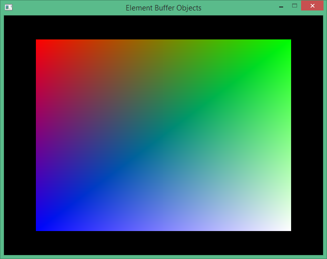
That’s it, we have successfully used element buffer objects and rendered a cute looking rectangle using Indexed Rendering. This is the end of this tutorial, and in the next tutorial let us learn how to use interleave the data into a single vertex buffer. See you there in the next tutorial.
Source Code
The source code for this tutorial can be checked out from the source code repository on GitHub.