
This series refer to an older version of LWJGL 3. The updates are in progress.
Contents
Welcome to the fourth part of the LWJGL Tutorial Series. In the previous part, we have implemented our basic framework by using GLFW which manages the creation of window and callbacks for us. It also provides methods which allows us to query the input. From this part of the tutorial series, we are going to step into the world of graphics with OpenGL. I will start with the simplified Rendering Pipeline.
Everything in OpenGL is rendered using some primitives of geometry specified by sending the raw vertices. Vertices are small points that are used to construct the primitives in the later stage. These vertices are specified in terms of coordinates, and they will be sent to the next stage, the Vertex Shader.
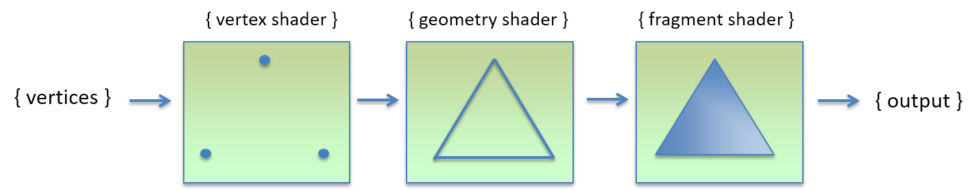
The Vertex Shader is responsible for transforming the vertices, it is where you apply transformations like translation, rotation, scaling, projection, and other effects to the vertices that are passed in. It creates the final correct vertices that are ready to form the primitives. Now the correct vertices are be passed into their next stage.
The second stage is the Geometry Shader. In this stage, the vertices that are transformed in the previous stage, will be used to create primitive shapes like triangles. After the creation of the shapes, these shapes are rasterised, meaning that they are made into flat images. From here, these rasterised images will go into the final stage of the pipeline, the Fragment Shader.
The Fragment Shader is the last stage in the pipeline, and it adds colors to the rasterised images produced in the previous stage. It is the work of fragment shader to calculate the correct color, apply textures, and also to calculate the lighting in the scene. The result of the fragment shader is copied into the output screen framebuffer.
Programming the Pipeline
By default, there is no pipeline in OpenGL, you are expected to program the pipeline. You create a Program, a small application that executes on the graphic card, allowing you to control the rendering pipeline. This program contains some modules that are linked with it, and those small modules are called as the shaders.
In order to program the pipeline, we will be writing the source code of the shaders in a language called as GLSL, short for OpenGL Shading Language. This language is very similar to C language and is very simple. Now, we create the shader objects in OpenGL and we upload the source code to it. And then, they are compiled.
After compilation of the individual shaders, we create a program object and attach these compiled shaders to it. Then, we link the program, making it ready to be used as the pipeline. This, is the process of the pipeline.
The GLSL Shading Language
The term GLSL is short for the OpenGL Shading Language, and is the language we should use to write our shaders. In this section, I will give you an introduction to the syntax of GLSL with the basic data types, vector datatypes and also matrices. I will also introduce the layout qualifiers here. For now, I will start with the version specifier directive.
#version 330 core
The above line is necessary in all our shader files, it specifies the language version of the shaders we are going to use, and in this case, it specifies that we intend to use version 330 in the core profile. The following table specifies the shader language versions and their matching OpenGL versions.
| OpenGL Version | OpenGL Context Profile | GLSL Version | Shader Preprocessor |
|---|---|---|---|
2.0 |
Compatibility | 110 |
#version 110 |
2.1 |
Compatibility | 120 |
#version 120 |
3.0 |
Compatibility | 130 |
#version 130 |
3.1 |
Compatibility | 140 |
#version 140 |
3.2 |
Compatibility | 150 |
#version 150 |
3.3 |
Compatibility | 330 |
#version 330 |
3.3 |
Core | 330 core |
#version 330 core |
There are more versions upto OpenGL 4.5 which is latest, but I will use 3.3 because of compatibility with more GPUs. Moreover, Mac systems will only support upto 4.1 which is another issue. So I went with version 330 core, as it is what is compatibile with my OpenGL version, which is 3.3 core.
Basic Datatypes in GLSL
GLSL Provides some basic data types like float, int, unsigned int, boolean, and void. You just declare them as you would in C or Java, they are pretty much the same. See this snippet for example.
int   myInteger         = -2;
bool  myBoolean         = true;
bool  myBoolean2        = false;
uint  myUnsignedInteger = 3;
float myFloat           = 0.8;
They are just very similar, but usually we only use floats, because the graphics cards are optimised for using floating point arithmetic and they usually give us performance. You should notice a small difference though, in Java we have a f suffix for floating point numbers, which is not present here.
Vector Datatypes in GLSL
Along with these basic data types, GLSL also provides vector datatypes. There are datatypes defined for 2D, 3D and also 4D vectors that take up either integers or floats. See this snippet for example.
vec2 myVec2 = vec2(0.1, 1.8);
vec3 myVec3 = vec3(0.1, 0.2, 0.3);
vec4 myVec4 = vec4(0.3, 0.2, 0.7, 0.2);
In addition to that, you can also create higher dimension vectors using lower dimension vectors. You simply pass them, and then the missing component. Here is another snippet.
vec2 myVec2 = vec2(0.1, 1.4);
vec3 myVec3 = vec3(myVec2, 1.3);
vec4 myVec4 = vec4(myVec3, 8.2);
You can access the individual components of the vectors using the dot operator. The components will be named x, y, z and w, but can also be called as r, g, b and a. For 2D vectors, they can be called s and t, or u and v, anything is valid.
Matrices in GLSL
GLSL also provides matrix datatypes for 2x2, 3x3 and 4x4 matrices. Though it is possible to create and compute the matrices inside the shaders, we usually compute the matrices once and pass them to the shaders so that they will be reused for every vertex we use. The type names are mat2 mat3 and mat4 respectively. They are pretty simple to use actually, that I will show them when the time comes.
GLSL Storage Qualifiers
In GLSL, every global variable belongs to either one of these four storage qualifiers which decides where that variable is stored. See this table for the description of the storage qualifiers.
| Storage Qualifier | Description |
|---|---|
const |
Specifies that the variable is a constant and it’s value will not be changed. |
in |
Specifies that the variable is an input from a previous stage in the pipeline. |
out |
Specifies that the variable is an output to the next stage in the pipeline. |
uniform |
Specifies that the variable is a linkage between the application and the shader. |
Using the above, let’s now write a pass-away vertex shader, which just passes away the inputs it received without any other transformations to be applied.
#version 330 core

in vec3 position;
in vec4 color;

out vec4 vColor;

void main()
{
    vColor = color;
    gl_Position = vec4(position, 1.0);
}
The above vertex shader says a lot of information. The first line says that we intend to use the 330 version of the language in the core profile. Then, we have two variables with the storage qualifier as in meaning that we are taking those variables as input. We are taking a three dimensional vector called position and a four dimensional vector called color as our inputs.
Now if you look at the sixth line, we are declaring an output variable called as vColor. We are using out qualifier since we intend to send that to the fragment shader as output. Then on the line eight, we declare a function called main, this is where the execution of this shader begins.
Inside the main function, we are simply passing the input color to the output color, we just pass-away the value. Then in the line eleven, we are writing to a built-in variable called gl_Position which is the output for the vertex shader. We are just converting the 3D position value we received into a 4D vector and passing it away. This is the basic vertex shader.
Input Layout Qualifier
If we look at the previous vertex shader, you can see that we did not specify the location of the input, I mean, from which location we are going to listen. In that case, you have to query your program for the location of those inputs. Fortunately, there exists another qualifier which allows you to specify the location directly in the source code.
#version 330 core

layout(location = 0) in vec3 position;
layout(location = 1) in vec4 color;

out vec4 vColor;

void main()
{
    vColor = color;
    gl_Position = vec4(position, 1.0);
}
This is the same example vertex shader as in our previous example, but the only change is that here I have specified the location of the input in the shader itself. One thing to note, this input layout qualifier is only allowed in the vertex shader. Keep that in mind while writing these shaders.
Conclusion
There is still much more in GLSL that I did not explain you, there are functions, structures, output layout qualifier, interface blocks, and also arrays, and much more. I’m not going to touch them in this first introductory tutorial, but I will explain them when we actually need them.
If you are too much interested in learning them right now, I don’t object, you can read the GLSL 330 Language Specification yourself. So this is the end of the fourth part of the LWJGL Tutorial Series, and in the next part, we will be seeing our first triangle on the screen.
Source Code
There is really no source code in this tutorial, because I only want to intend it to introduce GLSL to you. If you are looking for the source code of the previous tutorials, you can find that on my GitHub repository here.